Yesterday I recieved an HDMI switch I ordered on sale for about $20. It is the
Monoprice HDMI Switcher HDX-402E. It has 4 inputs and 2 outputs. It will be used in my apartment to connect my raspberry pi and Xbox 360, as well as my roomates' PS3 and Apple TV to a projector and a TV. Another feature it has is an RS-232 port on the back, which allows for remote control via a Windows PC. Unfortunately, it is intended to only communicate with the Windows application. So I decided to see if I can make it work without the application.
The Raspberry Pi is running Raspbmc right now, and I plan on utilizing the GPIO pins in order to communicate with the HDMI switch, so that I can have the remote app for XBMC also control the HDMI input, as well as use it with scripts, such as having the input change to the Pi when it boots up.
 |
| 4x2 HDMI Switch |
 |
| 2 Outputs, 4 Inputs, RS-232, +5V Power |
So I install the software, which in itself was a pain because it came on an 8cm CD, and my computers either are slot loading or have a vertical drive. eventually I found a computer to load it with and copy it to a flash drive. For those who want to just download it, I
uploaded it here.
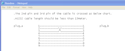
I open up the software, and it seems to be unable to find the switch. I eventually go and check the Readme, and found the second frustration of the day! Turns out that you can't use any DB9 cable, but you need to have the Tx and Rx pins crossed.
 |
| There are cable standards for a reason... |
Since my work deals with lots of networking equipment, which still uses DB9 for serial console access, I grabbed one, and made my own to test with. A nice trick for working with this is to take a knife and cut the insulation at 2 parts in the wire, 2-4 inches apart. Then slice along the wire and remove the insulation, and you get a 2-4 inch section of unexposed wire. Fold it in half, place a ziptie on it to hold it in place, and now you can quickly cut wires in the middle, and twist them onto other wires.
This cable happens to follow the coloring standards, meaning that Red and Brown are my Tx and Rx wires.
 |
| Modified DB9 cable ready to use for the HDMI switch |
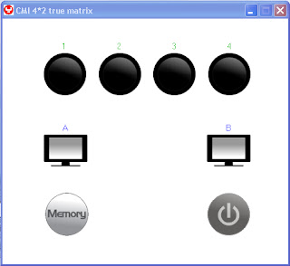
Now the application recognizes the switch and opens right up. It has a similar UI to the IR remote control. You click an input, then an output to link the two together. Memory and Power just toggle on and off.
 |
| Windows HDMI Switch Application |
Now that I know it is functional, I can begin to find out how it works. According to the Readme, when the application is fired up, it will wait for a transmission from the switch, analyze the protocol, and if the handshake is ok, opens up the operation. If that is the case, I just need to spoof the application's handshake process, read the data from the switch, and be able to reply with the correct commands.
In Windows, the way the serial protocol works is that once a COM port is opened with an application, no other application can have access to that com port. For instance, if you open HyperTerminal and open a connection on COM1, then if you open PuTTY and try to open COM1, you will get an error. However, I did find this application called
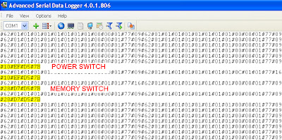
Aggsoft Advanced Serial Data Logger. This application has a "spy mode" with a special driver that lets it monitor all inbound and outbound traffic on a COM port, without restricting it from other applications. I downloaded the trial and got started. I configured it to give me raw hex values instead of trying to convert it; this way I know the data I get is correct. As soon as I fire up the switch application, I find that I get a series of 14 bytes that repeat over and over. It seems to me that either the so called "handshake" does not exist, or it is something repeated over and over. Since I don't have the ability to connect any HDMI devices right now, the only things I can do are press the memory and power button. As soon as I press them I get my output bytes for them! They are the same when pressed multiple times, indicating that there is not a different on and off command.
 |
| Log of the data when buttons are pressed in the application |
So now I know the command to send power is
10 EF D5 7B
and the command for memory is 28 D7 D5 7B
Hopefully the rest of the commands are that simple.
Now, to look at the 14 byte string again...
62 01 01 01 01 01 01 01 01 00 00 01 77 09
This is repeating forever. I found that some of those bytes change when a button is pressed. On turning the power on, which selects input 1 for both A and B, I now get this string:
62 01 01 01 01 01 01 01 01 0C 01 01 77 16
The highlighted bytes are the ones that differ from the first string. This seems like each byte represents a value for each property of the switch, which is probably how the application knows which ports have active inputs and what other buttons are pressed. To list the modes/options we have:
- "Handshake"
- Power On/Off
- Active Input on Output A
- Active Input on Output B
- No input signal for ports 1-4
- Signal not selected for ports 1-4
- Active Signal path for ports 1-4
- Bytes used as memory to remember current configuration as default for boot up time(this gets saved when the memory key is pressed)
So out of a 14 byte string, I assume that there will be 1 start byte, handshake, and power. Active Inputs for A and B will also take 1 byte each. I assume 4 bytes will be used to determine the status of each of the 4 ports, and another 4 bytes for storing the current configuration. I don't think there is an end byte, since the last byte changes with the power toggled on and off.
It seems like a possibility, since it totals to 13 bytes. There's only one way to find out now, and that's by testing with 4 inputs and 2 outputs, plugging them in and unplugging them, turning the devices on, and switching through the inputs.
Look out for an update as soon as I find more information!


